
| Version | 1.0 |
| Date | 2026-06-22 |
| Scope | 3 subsidiaries (US, Japan, UK) · AWS, GCP, Azure · on-premises offices |
| Companion diagram | global-network-hub-spoke-topology.svg |
| Supernet | 10.0.0.0/8 (RFC 1918) |
1. Purpose and scope
This document describes the target-state global network connecting three subsidiary offices and their respective public-cloud and on-premises environments. It establishes a single, hierarchical addressing plan, a hub-and-spoke model for inter-office connectivity, a consistent pattern for office-to-cloud connectivity across all three cloud providers, and a uniform approach to remote user access, DNS, and segmentation. The intent is that every site is built from the same repeatable template, so that adding a subsidiary, a region, or a cloud is an exercise in delegating address space and instantiating known patterns rather than designing anew.
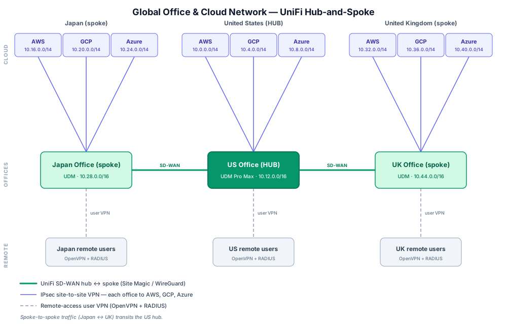
The accompanying diagram shows the topology this document describes: the United States office operating as the hub, the Japan and United Kingdom offices as spokes, each office holding site-to-site VPNs into its own AWS, GCP, and Azure footprints, and a remote-access user VPN terminating at each office.
2. Architecture at a glance
The network is organized as three parallel site columns joined by a hub-and-spoke core. Each column represents one subsidiary and contains that subsidiary's cloud environments (AWS, GCP, Azure), its on-premises office anchored by a UniFi Dream Machine Pro Max, and its population of remote users. The three offices are interconnected by UniFi SD-WAN, with the US office acting as the hub and the Japan and UK offices as spokes; traffic between the two spokes transits the hub rather than flowing directly between them.
Three classes of tunnel carry traffic in the design. UniFi SD-WAN tunnels (Site Magic, WireGuard-based) form the office-to-office hub-and-spoke core. IPsec site-to-site VPNs connect each office to its three cloud providers. Remote-access VPNs (OpenVPN authenticated by RADIUS) bring individual users into their local office. Because every prefix in the estate is a child of a single supernet, the routing that ties these tunnels together summarizes cleanly at each tier.
3. Addressing foundation
The entire estate is carved top-down from 10.0.0.0/8. Each subsidiary receives a /12; within a subsidiary, each cloud provider and the on-premises footprint receive a /14; and below that, regions, environments, VPCs, and subnets follow fixed prefix lengths so that any allocation can be expressed as a single summarized route at any level. A separate /12 is reserved for shared transit and management services, and a large run of /12 blocks is held back for future subsidiaries and acquisitions.
The per-site allocations shown on the diagram are:
| Subsidiary | Subsidiary /12 |
AWS /14 |
GCP /14 |
Azure /14 |
On-prem /14 |
Office /16 |
|---|---|---|---|---|---|---|
| United States (hub) | 10.0.0.0/12 |
10.0.0.0/14 |
10.4.0.0/14 |
10.8.0.0/14 |
10.12.0.0/14 |
10.12.0.0/16 |
| Japan (spoke) | 10.16.0.0/12 |
10.16.0.0/14 |
10.20.0.0/14 |
10.24.0.0/14 |
10.28.0.0/14 |
10.28.0.0/16 |
| United Kingdom (spoke) | 10.32.0.0/12 |
10.32.0.0/14 |
10.36.0.0/14 |
10.40.0.0/14 |
10.44.0.0/14 |
10.44.0.0/16 |
Shared services and transit occupy 10.240.0.0/12. Container and overlay networking (Kubernetes pods and services across EKS, GKE, and AKS) is allocated from the CGNAT range 100.64.0.0/10 so that large pod populations never consume routable RFC 1918 space or risk collision across sites. Because each subsidiary is a contiguous /12 and each cloud a contiguous /14, the routing tables that span the VPN tunnels remain compact: a single /12 route describes an entire subsidiary, and a single /14 describes an entire cloud presence.
4. Sites and the on-premises edge
Each office is anchored by a UniFi Dream Machine Pro Max, which combines the gateway, zone-based firewall, network controller, VPN concentrator, and RADIUS server in one device. The office address space is a /16 drawn from the subsidiary's on-premises /14, subdivided into purpose-built VLANs — Management, Corporate WiFi, Application, Data, Printers/IoT, Guest WiFi, a remote-access VPN client pool, and a Cloud Transit segment that anchors the site's connectivity to the clouds. Subnets are sized as /24 per VLAN, with the VLAN identifier encoded in the third octet for readability.
The US office is additionally the inter-site hub, so it carries the aggregate of spoke-to-spoke and spoke-to-cloud transit in addition to its own local traffic; it is provisioned with the headroom and redundancy (multi-WAN, gateway failover) appropriate to that role. The Japan and UK offices are structurally identical spokes built from the same template against their own /16 office blocks.
5. Inter-site connectivity — UniFi hub-and-spoke
The three offices are joined by UniFi's license-free SD-WAN (Site Magic), which establishes WireGuard tunnels between sites. The US office is configured as the hub and the Japan and UK offices as spokes. This means each spoke maintains a tunnel to the hub, and any Japan-to-UK communication is routed through the US hub rather than over a direct spoke-to-spoke tunnel. The hub-and-spoke choice trades a small amount of latency on inter-spoke paths for a simpler, centrally controlled topology in which policy, inspection, and route advertisement converge at one place; it also scales linearly as further spokes are added, since each new office needs only a single tunnel to the hub rather than a full mesh.
Across these tunnels the offices exchange summarized routes: each site advertises its office /16 and learns the others, so any host in one office can reach any host in another according to the firewall policy in force at each end.
6. Cloud connectivity — per-site site-to-site VPN
Every office holds three independent IPsec site-to-site VPNs, one to each of its cloud providers. Crucially, each office connects to its own regional cloud footprint rather than to a shared cloud estate: the US office tunnels into the US AWS, GCP, and Azure /14s; the Japan office into the Japan cloud /14s; and the UK office into the UK cloud /14s. On the cloud side, each tunnel terminates either directly on the VPC/VNet gateway (for a single environment) or on the provider's regional transit construct — AWS Transit Gateway, Azure Virtual WAN hub, or GCP Network Connectivity Center — when the office needs to reach every environment in that region behind one attachment.
The tunnels are hardened IKEv2 IPsec (AES-256, SHA-256, DH group 14) and can run with static routing or, preferably for production, BGP, so that each side advertises and withdraws prefixes dynamically and so that the two redundant tunnel endpoints every cloud provides fail over automatically. Each office advertises its office /16 to the cloud and receives the cloud's /14 in return. Because the office /16 already contains the remote-access VPN client pool, remote users inherit cloud reachability through the same office-to-cloud tunnels without any additional cloud configuration.
7. Remote access — user VPN
Each office terminates a remote-access user VPN so that employees can reach their local site, and through it the connected clouds, from anywhere. The reference implementation is OpenVPN with user authentication delegated to the UDM's built-in RADIUS server: the TLS tunnel is secured by a certificate authority and server certificate, while individual identity is verified by RADIUS username and password (optionally backed by an external RADIUS server for multi-factor authentication). Connected clients are assigned addresses from the office's VPN VLAN and are pushed routes to the office subnets and the cloud /14s, plus the office DNS server for name resolution. Where a fully vendor-supported, GUI-driven path is preferred, the native UniFi L2TP "Remote User VPN" bound to a RADIUS profile provides the same RADIUS-authenticated outcome.
Remote users are treated as a distinct security zone: they are granted access equivalent to on-site corporate users, with sensitive tiers (such as the Data VLAN) reachable only indirectly through the Application tier and administrative access to the Management VLAN gated separately.
8. DNS architecture
Name resolution follows a split-horizon model. Office clients are pointed at the UDM's built-in DNS service, which resolves local records and forwards internet queries to an upstream resolver. For private cloud names, the UDM performs conditional (per-domain) forwarding: queries for a cloud's private domain are forwarded across the site-to-site tunnel to a Route 53 Resolver inbound endpoint inside the corresponding VPC (or the equivalent private DNS resolver in Azure and GCP), which returns the private addresses of cloud resources. The reverse direction — cloud workloads resolving on-premises names — is provided by an outbound resolver endpoint and forwarding rule that sends the on-premises domain back to the UDM's DNS. This gives every client, on-site or remote, a single consistent view of names whether the resource lives in the office or in the cloud.
9. Security and segmentation
Segmentation is enforced consistently at every layer of the estate. On-premises, the UDM's zone-based firewall governs traffic between VLANs: Guest and IoT networks are isolated to internet-only or no egress and cannot initiate to internal segments; the Data tier is reachable only from the Application tier and carries no internet path; the Management network is administered only by authorized users; and remote VPN users are confined to the access their zone permits. The same intent is mirrored in each cloud using that provider's native controls — AWS security groups and network ACLs, Azure network security groups (with Azure Firewall available for centralized inspection), and GCP VPC firewall rules — so that the public/application/data/management tiering is identical regardless of where a workload runs. Tunnels are encrypted end to end, and the hierarchical addressing allows firewall and routing policy to be written against summarized prefixes (a whole tier, a whole cloud, a whole subsidiary) rather than long lists of individual subnets.
10. Routing and summarization
The addressing hierarchy is what makes routing across this many tunnels tractable. Each office advertises a single /16 to its peers and to its clouds; each cloud advertises a single /14. At the hub, the US office aggregates the spoke prefixes, so the route tables that describe the entire global estate remain short and human-readable. Where dynamic routing is used, BGP carries these summaries automatically and handles failover; where static routing is used, the small number of summary prefixes keeps manual configuration manageable. Each subsidiary functions as its own routing domain, summarized at the /12 boundary, so that renumbering or change inside one subsidiary does not ripple into the others.
11. Resilience and high availability
Redundancy is layered through the design. Each cloud site-to-site VPN uses the two tunnel endpoints the provider supplies, with BGP enabling automatic failover between them. Within each cloud region, egress and inter-AZ resilience are provided by per-zone NAT gateways (AWS) and zone-redundant NAT (Azure/GCP), and workloads are spread across availability zones. At the office edge, the UDM Pro Max supports multi-WAN with cellular backup and gateway failover (Shadow Mode/VRRP), protecting the hub role on which inter-site and cloud connectivity depends. The hub-and-spoke core can be hardened further by giving the hub redundant WAN paths, since a hub outage would otherwise isolate the spokes from one another.
12. Governance and source of truth
All address space is allocated top-down and recorded in a single IPAM system of record (for example NetBox, with one tenant per subsidiary), mirrored into each cloud's native IPAM and enforced at provisioning time through infrastructure-as-code so that allocations are assigned from the plan rather than chosen ad hoc. Scheduled reconciliation compares the live state of each cloud and the on-premises networks against the plan and flags drift. This governance is what keeps the clean summarization described above intact over time: every VLAN, VPC, VNet, and tunnel endpoint traces back to the same authoritative hierarchy.
13. Design principles and trade-offs
The architecture rests on a few deliberate choices. Strict top-down, summarizable addressing is favored over convenience so that overlap is structurally impossible and routing stays simple. A hub-and-spoke inter-office core is favored over a full mesh for central control and linear scalability, accepting added latency on the comparatively rare spoke-to-spoke path. A single repeatable site template — UDM edge, tiered VLANs, three cloud VPNs, RADIUS-authenticated user VPN, split DNS — is favored over per-site bespoke design so that operations and onboarding are uniform. And reserved space for acquisitions is favored over tight packing, because mergers are the most common source of addressing conflict. The principal trade-off to revisit as the estate grows is the centrality of the US hub: as inter-spoke traffic increases, selectively enabling direct spoke-to-spoke tunnels (a partial mesh) or promoting a second hub may become worthwhile, at the cost of some of the simplicity the pure hub-and-spoke model provides.